
Distance annotations and scale
Distance annotations label lengths in an image. The displayed value converts segment length using a configured scale. For physical dimensions, supply a reliable known length or scale yourself.
Draw a dimension line
- Choose Distance annotation in the screenshot toolbar.
- Hold the left mouse button at the measurement start, drag to the end and release. A dimension line with a value appears.
- Keep Distance annotation active and click the line to select it. Check both endpoints against the target edges.
- Choose the unit and enter the intended value in Actual distance value. The label updates.
- Adjust decimal places and endpoint appearance, deselect to inspect it, then copy or save.
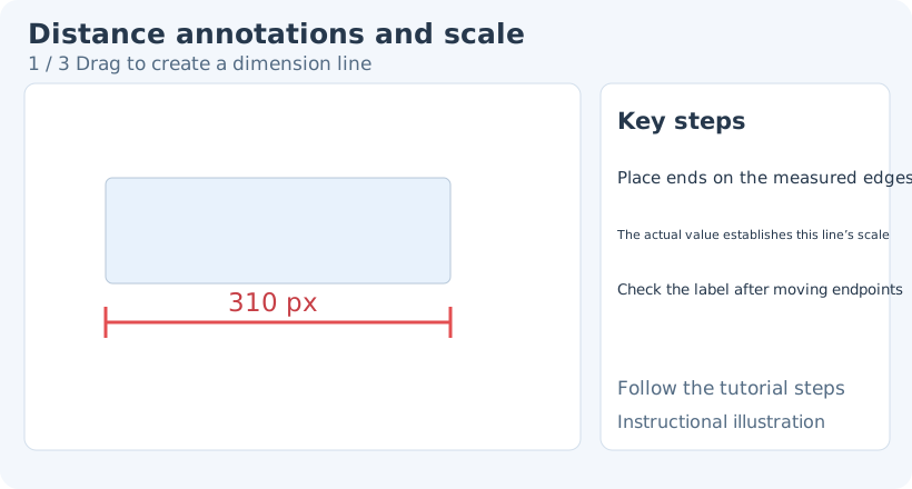
1. Drag to create a dimension line
To change an existing object’s tool-specific style, switch back to Distance annotation, then click the object to select it again. Select elements provides general transforms, stacking and opacity. Switching drawing tools clears the previous selection, so select the object again.
Actual distance and scale
“Actual distance value” calculates a scale from the current segment. For example, if a line represents a known 10 cm, select it, choose cm and enter 10. Subsequent changes to that annotation’s geometric length update its displayed value using the scale.
The app cannot automatically infer real dimensions from any screen image. Perspective, screenshot scaling and source resolution affect the correspondence. For engineering precision, establish the source scale and check key positions first.
Without a selected dimension line, some settings apply to new annotations. Confirm selection handles before calibrating a particular line.
Units, precision and appearance
The unit control includes pixels and several length units. Choose px, cm, mm, m or another unit appropriate to the task. Choosing a unit does not replace scale calibration.
Decimal places supports integers or 1, 2 or 3 decimals. More displayed digits do not improve the source image’s measurement accuracy.
Stroke color and width determine readability. Endpoint style changes the symbols; Endpoint scale changes their size. Reduce the scale if symbols obscure the measurement positions.
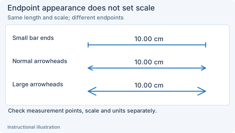
Endpoint style and size do not calibrate distance. Check measurement points, scale and unit separately. Enlarge the comparison.
Edit endpoints and label placement
Select the dimension annotation with Select elements. Drag endpoints to correct the measured range, or drag its body to move the whole annotation. Change its value through Actual distance value or the corresponding numeric-edit entry, rather than covering the label with separate text.
Check the label after geometry changes. If the length changes unexpectedly, check scale, unit and whether an endpoint snapped to another object.
Correct and export
Undo mistakes or select and delete one annotation. For an incorrect value, check in order: endpoint positions → unit → actual value and scale → decimal places. Fix scale before display formatting.
Related: Angles · Brackets · Element editing.