
Angle annotations
Angle annotations describe the angle between two sides, useful for geometry, interface rotation and shape relationships. Creation uses first endpoint → vertex → second endpoint. The second position is the angle’s center.
Place the three points in order
- Choose Angle annotation and set angle type and unit in the style toolbar.
- Click the outer endpoint of the first side. Its preview follows pointer movement.
- Click the vertex, where the sides meet, to fix the angle’s center.
- Move toward the second side’s outer endpoint, inspect the arc and value, then click to finish.
- Switch to Select elements, check all three positions, correct them and copy or save.
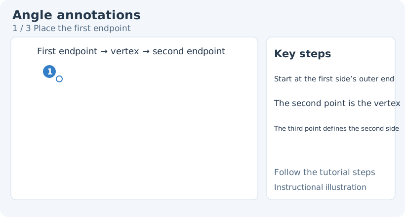
1. Place the first endpoint
To change an existing object’s tool-specific style, switch back to Angle annotation, then click the object to select it again. Select elements provides general transforms, stacking and opacity. Switching drawing tools clears the previous selection, so select the object again.
360° and 180° types
360° angle is directed and can represent turning within a full revolution. 180° angle displays the interior angle between the sides. The same three points can show different values depending on type; choose the turning direction or included angle you intend to explain.
For the smaller included angle, start with the 180° type. For a direction of rotation or a turn beyond half a revolution, inspect the 360° preview. You can still select a finished object and change its type.
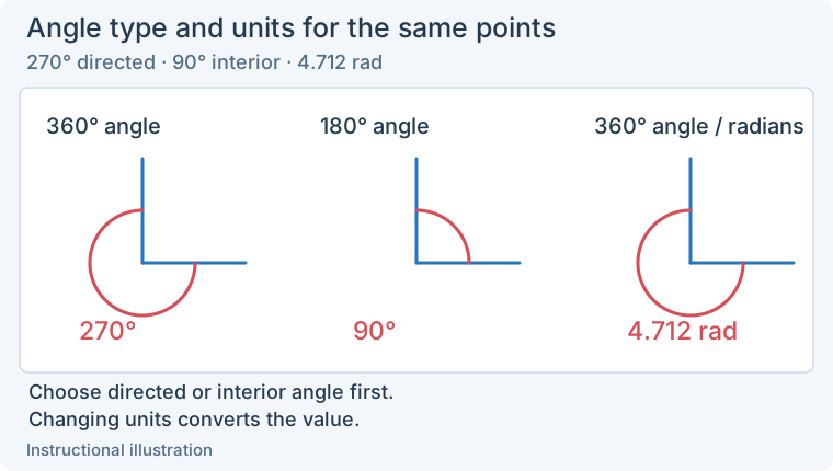
Choose the intended directed or interior angle first. Changing units performs a mathematical conversion rather than retaining the same number. Enlarge the comparison.
Units and precision
Choose Degrees or Radians. Decimal places control the displayed format, from integers to multiple decimal places. Do not read a degree value as the same number of radians; check the unit and resulting label after switching.
Color and stroke width control the sides and arc. On a complex image, use a clearly visible color to locate the vertex and both sides, then choose a suitable final style.
Hold Shift while drawing to constrain direction or angle for regular geometry. Without constraints, place points accurately on the original image; do not move them away from the explained edges just for visual neatness.
Edit the angle and arc
Select the annotation with Select elements and drag its three points to adjust the sides or vertex. Drag the arc control to change its displayed radius.
Use the wheel to fine-tune the angle. During creation, place the first two points and scroll before placing the third. For existing annotations, select only angle objects and scroll while no drag is active. Each wheel notch changes the angle by 1°, or 0.1° while holding Shift. Inspect the arc and value before finishing the point or continuing to edit.
The following example uses 180° angle (interior angle) to distinguish arc editing from endpoint editing.
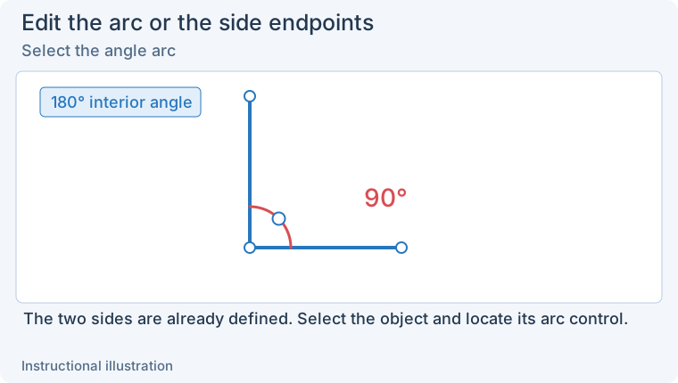
1. Select the angle arc — The two sides are already defined. Select the object and locate its arc control.
- — The two sides are already defined. Select the object and locate its arc control.
- — Drag the arc away from the vertex to increase its radius. The sides and 90° value remain unchanged.
- — Drag the second side endpoint to change its direction and the angle value. This differs from changing only the arc radius.
Moving the text does not change the angle. If the value is incorrect, first check that the second point is the vertex, then check angle type and unit.
Before all three points are placed, right-click to cancel that angle while keeping other annotations. In screenshot capture, the default Esc cancels the whole capture, with a confirmation dialog first if enabled. In the image editor, Esc can discard the unfinished angle. Undo a finished annotation, or select and delete it. Related: Distance · Brackets · Element editing.